| |

|
Annex J
(normative)
PSL 2 Pipe ordered for offshore service |
J.1 Introduction
This annex specifies additional provisions that apply for PSL 2 pipe that is ordered for offshore service [ see 7.2 c) 54.]
NOTE This annex does not include requirements for specialized tests for pipe intended for applications such as pipe reeling or for pipe that will experience high (> 0,5 %) total, single event strain during installation. For such applications, additional testing can be necessary to prove the suitability of the pipe and the purchaser might need to supplement the requirements of this International standard with other appropriate provisions (e.g. see DNV-OS-F101[14]).
|
J.2 Additional information to be supplied by the purchaser
The purchase order shall indicate which of the following provisions apply for the specific order item:
a ) steel casting method for strip or plate used for the manufacture of welded pipe (see J.3.3.2.1.);
b ) ultrasonic inspection of strip or plate for laminar imperfections (see J.3.3.2.4);
c ) supply of helical-seam pipe containing strip/plate end welds (see J.3.3.2.5);
d ) chemical composition for intermediate grades (see J.4.1.1);
e ) chemical composition for pipe with t > 25,0 mm (0.984 in) (see J.4.1.2);
f ) carbon equivalent limit for steel Grade L555QO or X80QO (see Table J.1);
g ) chemical composition limits [see Table J.1, footnotes d)];
h ) acceptance criteria for tensile properties if determined at other than room temperature (see J.4.2.2);
I ) for Grade L555QO or X80QO and L555MO or X80MO pipe, a lower maximum tensile strength limit may be agreed [see Table J.2, footnote b)];
j ) minimum average length other than 12,1 m (39.7 ft) and/or different range (see J.6.3);
k ) diameter and out-of-roundness tolerances for SMLS pipe with t > 25,0 mm (0.984 in) [see Table J.3, footnote b)];
l ) use of inside diameter to determine diameter and out-of-roundness tolerances for non expanded pipe with D ≥ 219,1 mm (8.625 in) [see Table J.3, footnote c)];
m ) hardness test of the pipe body seam weld and HAZ of EW and SAW pipe (see Table J.7);
n ) CTOD testing (see J.8.2.2 and Table J.7);
o ) use of the ring expansion test for transverse yield strength determinations [see Table J.8, footnote c)];
p ) additional longitudinal tensile testing for deep-water pipelay [see Table J.8, footnote d)]; |
Table J.1 ------ Chemical composition for pipe with t ≤ 25,0 mm (0.984 in)
| Steel grade |
Mass fraction, based upon heat and product analyses |
Carbon equivalent a |
| (Maximum) % |
(Maximum) % |
| C b |
Si |
Mn b |
P |
S |
V |
Nb |
Ti |
Other c |
CE llw |
CE pcm |
| SMLS and welding pipes |
| L245NO or BNO |
0,14 |
0,40 |
1,35 |
0,020 |
0,010 |
d |
d |
0,04 |
e,f |
0,36 |
0,19 g |
| L290NO or X42NO |
0,14 |
0,40 |
1,35 |
0,020 |
0,010 |
0,05 |
0,05 |
0,04 |
f |
0,36 |
0,19 g |
| L320NO or X46NO |
0,14 |
0,40 |
1,40 |
0,020 |
0,010 |
0,07 |
0,05 |
0,04 |
e,f |
0,38 |
0,20 g |
| L360NO or X52NO |
0,16 |
0,45 |
1,65 |
0,020 |
0,010 |
0,10 |
0,05 |
0,04 |
e |
0,43 |
0,22 g |
| L245QO or BQO |
0,14 |
0,40 |
1,35 |
0,020 |
0,010 |
0,04 |
0,04 |
0,04 |
f |
0,34 |
0,19 g |
| L290QO or X42QO |
0,14 |
0,40 |
1,35 |
0,020 |
0,010 |
0,04 |
0,04 |
0,04 |
f |
0,34 |
0,19 g |
| L320QO or X46QO |
0,15 |
0,45 |
1,40 |
0,020 |
0,010 |
0,05 |
0,05 |
0,04 |
f |
0,36 |
0,20 g |
| L360QO or X52QO |
0,16 |
0,45 |
1,65 |
0,020 |
0,010 |
0,07 |
0,05 |
0,04 |
e,h |
0,39 |
0,20 g |
| L390QO or X56QO |
0,16 |
0,45 |
1,65 |
0,020 |
0,010 |
0,07 |
0,05 |
0,04 |
e,h |
0,40 |
0,21 g |
| L415QO or X60QO |
0,16 |
0,45 |
1,65 |
0,020 |
0,010 |
0,08 |
0,05 |
0,04 |
e,h |
0,41 |
0,22 g |
| L450QO or X65QO |
0,16 |
0,45 |
1,65 |
0,020 |
0,010 |
0,09 |
0,05 |
0,06 |
e,h |
0,42 |
0,22 g |
| L485QO or X70QO |
0,17 |
0,45 |
1,75 |
0,020 |
0,010 |
0,10 |
0,05 |
0,06 |
e,h |
0,42 |
0,23 g |
| L555QO or X80QO |
0,17 |
0,45 |
1,85 |
0,020 |
0,010 |
0,10 |
0,06 |
0,06 |
e,h |
as agreed |
| welded pipe |
| L245MO or BMO |
0,12 |
0,40 |
1,25 |
0,020 |
0,010 |
0,04 |
0,04 |
0,04 |
f |
- |
0,19 |
| L290MO or X42MO |
0,12 |
0,40 |
1,35 |
0,020 |
0,010 |
0,04 |
0,04 |
0,04 |
f |
- |
0,19 |
| L320MO or X46MO |
0,12 |
0,45 |
1,35 |
0,020 |
0,010 |
0,05 |
0,05 |
0,04 |
f |
- |
0,20 |
| L360MO or X52MO |
0,12 |
0,45 |
1,65 |
0,020 |
0,010 |
0,05 |
0,05 |
0,04 |
e,h |
- |
0,20 |
| L390MO or X56MO |
0,12 |
0,45 |
1,65 |
0,020 |
0,010 |
0,06 |
0,08 |
0,04 |
e,h |
- |
0,21 |
| L415MO or X60MO |
0,12 |
0,45 |
1,65 |
0,020 |
0,010 |
0,08 |
0,08 |
0,06 |
e,h |
- |
0,21 |
| L450MO or X65MO |
0,12 |
0,45 |
1,65 |
0,020 |
0,010 |
0,10 |
0,08 |
0,06 |
e,h |
- |
0,22 |
| L485MO or X70MO |
0,12 |
0,45 |
1,75 |
0,020 |
0,010 |
0,10 |
0,08 |
0,06 |
e,h |
- |
0,22 |
| L555MO or X80MO |
0,12 |
0,45 |
1,85 |
0,020 |
0,010 |
0,10 |
0,08 |
0,06 |
e,h |
- |
0,24 |
a Based upon product analysis (see 9.2.4 and 9.2.5) The CE llw limits apply if the carbon mass fraction is greater is greater than 0,12 % and the CE pcm limits apply if the carbon mass fraction is less than or equal to 0,12 %.
b For each reduction of 0,01 % below the specified maximum for carbon, an increase of 0,05 % above the specified maximum for manganese is permissible, up to a maximum increase of 0,20 %.
c AI total ≤ 0,060 %; N ≤ 0,012 %; AI/N ≥ 2:1 (not applicable to titanium-killed or titanium-treated steel);
d Unless otherwise agreed , the sum of the niobium and vanadium concentrations shall be ≤ 0,06 %.
e The sum of the niobium, vanadium and titanium concentrations shall be ≤ 0,15 %.
f Cu ≤ 0,35 %; Ni ≤ 0,30 %; Cr ≤ 0,30 %; Mo ≤ 0,10 %; B ≤ 0,000 5 %.
g For SMLS pipe, the listed value is increased by 0,03 percentage points, up to a maximum of 0,25 %.
h Cu ≤ 0,50 %; Ni ≤ 0,50 %; Cr ≤ 0,50 %; Mo ≤ 0,50 %; B ≤ 0,000 5 %.
|
Api Specification
J.4.2 Tensile properties
J.4.2.1 The tensile properties shall be as given in Table J.2.
J.4.2.2 If additional tensile properties are required to be determined at other than room temperature, the acceptance criteria shall be as agreed.
Table J.2 ---Requirements for the results of tensile tests
| Pipe grade |
Pipe body of SMLS and welded pipes |
Weld seam of HFW and SAW pipes |
Yield strength a
Rto,5
MPa (psi)
|
Tensile strength a,b
Rm
MPa (psi)
|
Ratio a,c
Rto,5/Rm
|
Elongation on 50 mm
or 2 in
Af
% |
Tensile strength d
Rm
MPa (psi) |
| minimum |
maximum |
minimum |
maximum |
maximum |
minimum |
minimum |
L245NO or BNO
L245QO or BQO
L245MO or BMO |
245
(35 500) |
450 e
(65 300) e |
415
(60 200) |
760
(110 200) |
0,93 |
f |
415
(60 200) |
L290NO or X42NO
L290QO or X42QO
L290MO or X42MO |
290
(42 100) |
495
(71 800) |
415
(60 200) |
760
(110 200) |
0,93 |
f |
415
(60 200) |
L320No or X46NO
L320QO or X46QO
L320MO or X46MO |
320
(46 400) |
525
(75 000) |
435
(63 100) |
760
(110 200) |
0,93 |
f |
435
(63 100) |
L360NO or X52NO
L360QO or X52QO
L360MO or X52MO |
360
(52 200)
|
525
(76 000) |
460
(66 700) |
760
(110 200) |
0,93 |
f |
460
(66 700) |
L390QO or X56 QO
L390MO or X56MO |
390
(56 600) |
540
(78 300) |
490
(71 100) |
760
(110 200) |
0,93 |
f |
490
(71 100) |
L415QO or X60QO
L415MO or X60MO |
415
(60 200) |
565
(81 900) |
520
(75 400) |
760
(110 200) |
0,93 |
f |
520
(75 400) |
L450QO or X65QO
L450MO or X65MO |
450
(65 300) |
570
(82 700) |
535
(77 600) |
760
(110 200) |
0,93 |
f |
535
(77 600) |
L485QO or X70QO
L485MO or X70MO |
485
(70 300) |
605
(87 700) |
570
(82 700) |
760
(110 200) |
0,93 |
f |
570
(82 700) |
L555QO or X80QO
L555MO or X80MO
|
555
(80 500) |
675
(97 900) |
625
(90 600) |
825
(119 700) |
0,93 |
f |
625
(90 600) |
|
Table J.2 --Requirements for the results of tensile tests
|
a For intermediate grades, the difference between the specified maximum yield strength and the specified minimum yield strength shall be as given in the table for the next higher grade, and the difference between the specified minimum tensile strength and the specified minimum yield strength shall be as given in the table for the next higher grade, For intermediate grades up to Grade L485 or X70, the tensile strength shall be ≤ 760 MPa (110 200).
b If agreed for pipe in Grade L555 or X80, more stringent maximum tensile strength limits may apply.
c This limit applies for pipe with D >323, 9 mm (12.750 in).
d For intermediate grades, the specified minimum tensile strength for the weld seam shall be the same value as was determined for the pipe body using footnote a).
e For pipe with D<219,1 mm (8.625 in), the yield strength shall be ≤495 MPa (71 800 psi).
f The specified minimum elongation, Af, on 50mm or (2 in), expressed in percent and rounded to the nearest percent, shall be as determined using the following equation:
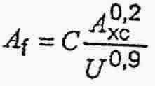
Where
C is 1 940 for calculations using SI units and 625 000 for calculations using USC units;
A xc is the applicable tensile test piece cross-sectional area, expressed in square millimeters (square inches), as follows:
---- for circular cross-section test pieces, 130 mm2 (0.20 in2) for 12,5 mm (0.500 in) and 8,9 mm (0.350 in) diameter test pieces; and 65 mm2 ( 0.10 in2) for 6,4 mm (0.250 in) diameter test pieces;
---- for full-section test pieces, the lesser of a) 485 mm2 (0.75 in2) and b) the cross-sectional area of the test piece, derived using the specified outside diameter and the specified wall thickness of the pipe, rounded to the nearest 10 mm2 (0.01 in2)
---- for strip test pieces, the lesser of a) 485 mm2( 0.75 in2 ) and b) the cross-sectional area of the test piece, derived using the specified width of the test piece and the specified wall thickness of the pipe, rounded to the nearest 10 mm2 (0.01 in2 );
U is the specified minimum tensile strength, expressed in megapascals (pounds per square inch).
|
|
.4.3 Hardness test
For test pieces subjected to a hardness test (see J.8.3.2), the hardness in the pipe body, weld and HAZ shall be
a ) ≤ 270 HV10 or ≤ 25 HRC for Grades ≤ L450 or X65
b ) ≤ 300 HV10 or ≤ 30 HRC for Grades > L450 or X65 > and ≤ L555 or X80.
|
|
|
Table J.3 Tolerances for diameter and out-of-roundness
Specified
outside diameter
D
mm (in) |
Diameter tolerances
mm (in) |
Out-of-roundness tolerances
mm (in) |
| Pipe except the end a |
Pipe end a,b,c |
Pipe except the end a |
Pipe end a,b,c |
| SMLS pipe |
Welded pipe |
SMLS pipe |
Welded pipe |
| <60,3 (2.375) |
± 0,5 (0.020) or
±
0,007 5 D,
whichever is the greater |
± 0,5 (0.020) or
± 0,007 5 D,
whichever is the greater, but
maximum of
± 3,2 (0.125) |
± 0,5 (0.020) or
± 0,005 5 D,
whichever is the
greater, but maximum
of ± 1,6 (0.063) |
d |
≥ 60,3 (2.375) to
≤ 610 (24.000)
|
0,015 D |
0,01 D |
>610 (24.000) to
≤ 1 422 (56.000) |
to
± 0,01 D |
± 0,005 D, but maximum of ± 4,0 (0.160) |
± 2,0 (0.079) |
± 1,6 (0.063) |
0,01 D
but maximum of
10 (0.4), for
 |
0,007 D
but maximum of
8 (0.3), for
|
by agreement for
|
by agreement for
|
| > 1 422 (56.000) |
as agreed |
|
a The pipe end includes a length of 100 mm (4.0 in) at each of the pipe extremities.
b For SMLS pipe, the tolerances apply for t ≤ 25.0 mm (0.984 in). and the tolerances for heavier pipe shall be as agreed.
c For pipe with D ≥ 219,1 mm (8.625 in), the diameter tolerance and the out-of-roundness tolerance may be determined using the calculated inside diameter (the specified outside diameter minus two times the specified wall thickness) or measured inside diameter rather than the specified outside diameter.(see 10.2.8.3.)
d lncluded in the diameter tolerance. |
|
Table J.4 -- Tolerances for wall thickness
Wall thickness
t
mm (in) |
Tolerances a
mm (in)
|
| SMLS pipe |
| < 4,0 (0.157) |
+ 0,6 (0.024)
- 0,5 (0.020) |
| ≥ 4,0 (0.157) to < 10,0 (0.394) |
+ 0,15 t
- 0,125 t |
| ≥ 10,0 (0.394) to < 25,0 (0.984) |
+ 0,125 t
- 0,125 t |
| ≥ 25,0 (0.984) |
+ 3,7 (0.146) or + 0,1 t, whichever is the greater b
- 3,0 (0.120) or - 0,1 t, whichever is the greater b |
| HFW pipe c,d |
| ≤ 6,0 (0.236) |
± 0,4 (0.016) |
| > 6,0 (0.236) to ≤ 15,0 (0.591) |
± 0,7 (0.028) |
| > 15,0 (0.591) |
± 1,0 (0.039) |
| SAW pipe c,d |
| ≤ 6,0 (0.236) |
± 0,5 (0.020) |
| >6,0 (0.236) to ≤ 10,0 (0.394) |
± 0,7 (0.028) |
| >10,0 (0.394) to ≤ 20,0 (0.787) |
± 1,0 (0.039) |
| > 20,0 (0.787) |
+ 1,5 (0.060)
- 1,0 (0.039) |
|
|
a if the purchase order specifies a minus tolerance for wall thickness smaller than the applicable value given in this table, the plus tolerance for wall thickness shall be increased by an amount sufficient to maintain the applicable tolerance range.
b For pipe with D ≥ 355,6 mm (14.000 in) and t ≥ 25,0 mm (0.984 in) the tolerance is +12.5% / -12.5% .
c The plus tolerance for wall thickness does not apply to the weld area.
d See 9.13.2 and J 7.2 for additional restrictions. |
|
J.8.1 Specific inspection
The frequency of inspection shall be as given in Table 18, except as specifically modified in Table J.7.
Table J.7 Inspection frequency
| Type of inspection |
Type of pipe |
Frequency of inspection |
| Tensile testing of the pipe body of pipe with D < 508 mm (20.000 in) |
SMLS, HFW, SAWL or SAWH |
Once per test unit of not more than 100 lengths of pipe with the same cold expansion ratio
a |
| Tensile testing of the pipe body of pipe with D ≥, 508 mm (20.000 in) |
SMLS, HFW, SAVVL or SAWH |
Once per test unit of not more than 50 lengths of pipe with the same cold expansion ratio
a |
| Tensile testing of the longitudinal or helical-seam weld of welded pipe with
219,1 mm (8.625 in) ≥, D < 508 mm (20.000 in) |
HFW, SAWL or SAWN |
Once per test unit of not more than 100 lengths of pipe with the same cold expansion ratio a,b |
| Tensile testing of the longitudinal or helical-seam weld of welded pipe with
D ≥, 508 rnm (20.000 in) |
HFW, SAWL or SAWH |
Once per test unit of not more than 50 lengths of pipe with the same cold expansion ratio a.b.c |
| Tensile testing of the strip/plate end weld of SAW pipe with D ≥ 219,1 mm (8.625 in) |
SAWH |
Once per test unit of not more than 50 lengths of pipe with the same cold-expansion ratio a.b.c |
| CVN impact testing of the pipe body of pipe with 114,3 mm
(4.500 in) ≤ D < 508 mm (20.000) and specified wall thickness as given in Table 22 |
SMLS, HFW, SAWL or SAWH |
Once per test unit of not more than 100 lengths of pipe with the same cold-expansion ratio a |
| CVN impact testing of the pipe body of pipe with
D ≥ 508 mm (20.000) and specified wall thickness as given in Table 22 |
SMLS, HFW, SAWL or SAWH |
Once per test unit of not more than 50 lengths of pipe from the same heat of steel and with the same cold-expansion ratio a |
| CVN impact testing of the longitudinal or helical-seam weld of welded pipe with 114,3 mm
(4.500 in) ≤ D < 508 mm (20.000) and specified wall thickness as given in Table 22 |
longitudi
HFW, SAWL or SAWH |
Once per test unit of not more than 100 lengths of pipe with the same cold-expansion ratio a,b |
| CVN impact testing of the longitudinal or helical-seam weld of welded pipe with D ≥ 508 mm (20.000) and specified wall thickness as given in Table 22 |
HFW, SAWL or SAWH |
Once per test unit of not more than 50 lengths of pipe with the same cold-expansion ratio a,b,c |
| CVN impact testing of the strip/plate and weld of welded pipe with D ≥ 114,3mm (4.500) and specified wall thickness as given in Table 22 |
and
SAWH |
Once per test unit of not more than 50 lengths of pipe with the same cold-expansion ratio a,b,c |
| If agreed, hardness testing of pipe body and of the longitudinal or helical-seam weld and HAZ of welded pipe |
HFW, SAWL or SAWH |
As agreed |
| Pipe diameter and out-of-roundness for pipe with D ≤ 168,3 mm (6.625 in) |
SMLS, HFW, SAWL or SAWH |
Once per test unit of not more than 100 lengths of pipe |
| Pipe diameter and out-of-roundness for pipe with D < 168,3 mm (6.625 in) |
SMLS, HFW, SAWL or SAWH |
Once per test unit of not more than 20 lengths of pipe |
| Non-destructive inspection |
SMLS, HFW, SAWL or SAWH |
In accordance with Annex K |
| If agreed, for information purposes only, CTOD test for pipe in Grades ≥ L360 or X52 |
SAWL or SAWH |
Once; formanufacturing procedure qualification only |
| a The cold-expansion ratio is designated by the manufacturer and is derived using the designated before- expansion outside diameter or circumference and the after- expansion outside diameter or circumference. An increase or decrease in the cold-expansion ratio of more than 0,002 requires the creation of a new test unit.
b In addition, pipe produced by each welding machine shall be tested at least once per week.
c For double-seam pipe, both longitudinal weld seams in the pipe selected to represent the test unit shall be tested
d Applies only to finished helical-seam pipe containing strip/plate and welds. |
|
|