| |

|
Annex H
(normative)
PSL 2 Pipe ordered for sour service |
H.1 Introduction
This annex specifies additional provisions that apply for PSL 2 pipe that is ordered for sour service [see 7.2 c) 51 ] .
NOTE The consequences of sudden failures of metallic components used for the oil and gas production associated with their exposure to H2S- containing production fluids led to the development of NACE MR0175/ISO 15156-1[21] and subsequently EFC publication 16[13] ISO 15156-2 used those sources to provide requirements and recommendations for materials qualification and selection for application in environments containing wet H2S in oil and gas production systems. Carbon and low alloy steels selected using ISO 15156—2 are resistant to cracking in defined H2S containing environments in oil and gas production but are not necessarily immune to cracking under all service conditions. Different service conditions might necessitate the alternative testing that is dealt with in ISO 15156—2:2003, Annex B. That annex specifies requirements for qualifying carbon and low alloy steels for H2S service by laboratory testing.
It is the purchaser’s responsibility to select the carbon and low-alloy steels suitable for the intended service.
|
|
H.2 Additional information to be supplied by the purchaser
in addition to items a ) to g) as specified by 7.1, the purchase order shall indicate which of the following provisions apply for the specific order item:
a ) steel casting method for strip or plate used for the manufacture of welded pipe (see H.3.3.2.1);
b ) ultrasonic inspection of strip or plate for laminar imperfections (see H.3.3.2.4);
c ) supply of helical-seam pipe containing strip/plate end welds (see H.3.3.2.5);
d ) chemical composition for intermediate grades (see H.4.1.1);
e ) chemical composition for pipe with t > 25,0 mm (0.984 in) (see H.4.1.2);
f ) chemical composition limits (see Table H.1, footnotes c), d,) e), f), i), j)and k);
g ) frequency of hardness testing of the longitudinal seam weld of HFW or SAW pipe (see Table H.3);
h ) SSC test for manufacturing procedure qualification (see Table H.3);
i ) alternative HIC/SWC test methods and associated acceptance criteria (see H.7.3.1.3);
j ) photomicrographs of reportable HIC cracks (see H.7.3.1.4);
k ) alternative SSC test methods and associated acceptance criteria for manufacturing procedure qualification (see H.7.3.2.2);
l ) for pipe with t ≥ 5,0 mm (0.197 in), ultrasonic inspection for laminar imperfections with in extended length of 100 mm (4.0 in ) at the pipe ends (see K.2.1.3 );
m ) magnetic particle inspection for laminar imperfections at each pipe end face/bevel (see K.2.1.4); |
Table H.1 ---Chemical composition for pipe with t ≤25,0 mm (0.984
in)
| Steel grade |
Mass fraction, based upon heat and product analyses
%
maximum |
Carbon
equivalent a
%
maximum |
| C b |
Si |
Mn b |
P |
S |
V |
Nb |
Ti |
Other c, d |
CE llw |
CE pcm |
| SMLS and welded pipes |
| L245NS or BNS |
0,14 |
0,40 |
1,35 |
0,020 |
0,003 e |
f |
f |
0,04 |
g |
0,36 |
0,19 h |
| L290NS or X42NS |
o,14 |
0,40 |
1,35 |
0,020 |
0,003 e |
0,05 |
0,05 |
0,04 |
- |
0,36 |
0,19 h |
| L320NS or X46NS |
0,14 |
0,40 |
1,40 |
0,020 |
0,003 e |
0,07 |
0,05 |
0,04 |
g |
0,38 |
0,20 h |
| L360NS or X52NS |
0,16 |
0,45 |
1,65 |
0,020 |
0,003 e |
0,10 |
0,05 |
0,04 |
g |
0,43 |
0,22 h |
| L245QS or BQS |
0,14 |
0,40 |
1,35 |
0,020 |
0,003 e |
0,04 |
0,04 |
0,04 |
- |
0,34 |
0,19 h |
| L 290QS or X42QS |
0,14 |
0,40 |
1,35 |
0,020 |
0,003 e |
0,04 |
0,04 |
0,04 |
- |
0,34 |
0,19 h |
| L320QS or X46QS |
0,15 |
0,45 |
1,40 |
0,020 |
0,003 e |
0,05 |
0,05 |
0,04 |
- |
0,36 |
0,20 h |
| L360QS or X52QS |
0,16 |
0,45 |
1,65 |
0,020 |
0,003 e |
0,07 |
0,05 |
0,04 |
g |
0,39 |
0,20 h |
| L390QS or X56QS |
0,16 |
0,45 |
1,65 |
0,020 |
0,003 e |
0,07 |
0,05 |
0,04 |
g |
0,40 |
0,21 h |
| L415QS or X60QS |
0,16 |
0,45 |
1,65 |
0,020 |
0,003 e |
0,08 |
0,05 |
0,04 |
g,i,k |
0,41 |
0,22 h |
| L450QS or X65QS |
0,16 |
0,45 |
1,65 |
0,020 |
0,003 e |
0,09 |
0,05 |
0,06 |
g,i,k |
0,42 |
0,22 h |
| L485QS or X70QS |
0,16 |
0,45 |
1,65 |
0,020 |
0,003 e |
0,09 |
0,05 |
0,06 |
g,i,k |
0,42 |
0,22 h |
| welded pipe |
| L245MS or BMS |
0,10 |
0,40 |
1,25 |
0,020 |
0,002 e |
0,04 |
0,04 |
0,04 |
- |
- |
0,19 |
| L290MS or X42MS |
0,10 |
0,40 |
1,25 |
0,020 |
0,002 e |
0,04 |
0,04 |
0,04 |
- |
- |
0,19 |
| L320MS or X46 MS |
0,10 |
0,45 |
1,35 |
0,020 |
0,002 e |
0,05 |
0,05 |
0,04 |
- |
- |
0,20 |
| L360MS or X52 MS |
0,10 |
0,45 |
1,45 |
0,020 |
0,002 e |
0,05 |
0,06 |
0,04 |
- |
- |
0,20 |
| L390MS or X56 MS |
0,10 |
0,45 |
1,45 |
0,020 |
0,002 e |
0,06 |
0,08 |
0,04 |
g |
- |
0,21 |
| L415MS or X60 MS |
0,10 |
0,45 |
1,45 |
0,020 |
0,002 e |
0,08 |
0,08 |
0,06 |
g,i |
- |
0,21 |
| L450MS or X65MS |
0,10 |
0,45 |
1,60 |
0,020 |
0,002 e |
0,10 |
0,08 |
0,06 |
g,i,j |
- |
0,22 |
| L485MS or X70 MS |
0,10 |
0,45 |
1,60 |
0,020 |
0,002 e |
0,10 |
0,08 |
0,06 |
g,i,j |
- |
0,22 |
a ) Based upon product analysis (see 9.2.4 and 9.2.5) The CEllw limits apply if the carbon mass fraction is greater than 0,12 % and the CEpcm limits apply if the carbon mass fraction is less than or equal to 0,12 %.
b )
For each reduction of 0,01 % below the specified maximum for carbon, an increase of 0,05 % above the specified maximum for manganese is permissible, up to a maximum increase of 0,20 %.
c ) AI total ≤ 0,060 %; N ≤ 0,012 %; AI/N ≥ 2:1 (not applicable to titanium-killed or titanium-treated steel); Cu ≤ 0,35 % (if agreed ,Cu ≤ 0,10 %); Ni ≤ 0,30 %; Cr ≤ 0,30 %; Mo ≤ 0,15 %; B ≤ 0,0005 %.
d ) For welded pipe where calcium is intentionally added, unless otherwise agreed, Ca/s ≥ 1,5 if S > 0,0015 % For SMLS and welded pipes, the calcium concentration shall be ≤ 0,006 %.
e ) The maximum limit for sulfur concentration may be increased to ≤ 0,008 % for SMLS pipe and, if agreed, to ≤ 0,006 % for welded pipe. For such higher-sulfur levels in welded pipe, lower Ca/s ratios may be agreed.
f ) Unless otherwise agreed, the sum of the niobium and vanadium concentrations shall be ≤ 0,06 %.
g ) The sum of the niobium, vanadium and titanium concentrations shall be ≤ 0,15 %.
h ) For SMLS pipe, the listed value may be increased by 0,03.
i ) If agreed, the molybdenum concentration shall be ≤ 0,35 %.
j ) If agreed, the the chromium concentration shall be ≤ 0,45 %.
k ) If agreed, Cr concentration shall be ≤ 0,45 % and Ni concentration shall be ≤ 0,50 %.
|
Table H.2 ----Requirements for the results of tensile tests
| Pipe steel grade |
Pipe body of SMLS and welded pipes |
Weld seam of HFW and SAW pipes |
Yield strength a
Rto,5
Mpa (psi)
|
Tensile strength a
Rm
Mpa (psi)
|
Ratio b
Rto,5/Rm
|
Elongation on 50 mm
or 2 in
Af
% |
Tensile strength c
Rm
Mpa (psi) |
| minimum |
maximum |
minimum |
maximum |
maximum |
minimum |
minimum |
L245NS or BNS
L245QS or BQS
L245MS or BMS |
245
(35 500) |
450 d
(65 300) d |
415
(60 200) |
760
(110 200) |
0,93 |
e |
415
(60 200) |
L290NS or X42NS
L290QS or X42QS
L290MS or X42MS |
290
(42 100) |
495
(71 800) |
415
(60 200) |
760
(110 200) |
0,93 |
e |
415
(60 200) |
L320NS or X46NS
L320QS or X46QS
L320MS or X46MS |
320
(46 400) |
525
(76 100) |
435
(63 100) |
760
(110 200) |
0,93 |
e |
435
(63 100) |
L360NS or X52NS
L360QS or X52QS
L360MS or X52MS |
360
(52 200)
|
530
(76 900) |
460
(66 700) |
760
(110 200) |
0,93 |
e |
460
(66 700) |
L390QS or X56QS
L390MS or X56MS |
390
(56 600) |
545
(79 000) |
490
(71 100) |
760
(110 200) |
0,93 |
e |
490
(71 100) |
L415QS or X60QS
L415MS or X60MS |
415
(60 200) |
565
(81 900) |
520
(75 400) |
760
(110 200) |
0,93 |
e |
520
(75 400) |
L450QS or X65QS
L450MS or X65MS |
450
(65 300) |
600
(87 000) |
535
(77 600) |
760
(110 200) |
0,93 |
e |
535
(77 600) |
| L485MS or X70MS |
485
(70 300) |
635
(92 100) |
570
(82 700) |
760
(110 200) |
0,93 |
e |
570
(82 700) |
Table H.2 ----Requirements for the results of tensile tests |
a For intermediate grades, the difference between the specified maximum yield strength and the specified minimum yield strength shall be as given in the table for the next higher grade, and the difference between the specified minimum tensile strength and the specified minimum yield strength shall be as given in the table for the next higher grade, For intermediate grades, the tensile strength shall be ≤ 760 MPa (110 200 psi).
b This limit applies for pipe with D >323, 9 mm (12.750 in).
c For intermediate grades, the specified minimum tensile strength for the weld seam shall be the same value as was determined for the pipe body using footnote a).
d For pipe with D<219,1 mm (8.625 in), the maximum yield strength shall be ≤495 MPa (71 800 psi).
e The specified minimum elongation, Af, on 50mm or 2 in, expressed in percent and rounded to the nearest percent, shall be as determined using the following equation:
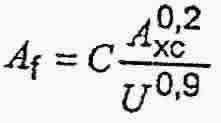
Where
C is 1 940 for calculations using SI units and 625 000 for calculations using USC units;
A xc is the applicable tensile test piece cross-sectional area, expressed in square millimeters (square inches), as follows:
---- for circular cross-section test pieces, 130 mm2 (0.20 in2) for 12,5 mm (0.500 in) and 8,9 mm (0.350 in) diameter test pieces; and 65 mm2 ( 0.10 in2) for 6,4 mm (0.250 in) diameter test pieces;
---- for full-section test pieces, the lesser of a) 485 mm2 (0.75 in2) and b) the cross-sectional area of the test piece, derived using the specified outside diameter and the specified wall thickness of the pipe, rounded to the nearest 10 mm2 (0.01 in2)
---- for strip test pieces, the lesser of a) 485 mm2( 0.75 in2 ) and b) the cross-sectional area of the test piece, derived using the specified width of the test piece and the specified wall thickness of the pipe, rounded to the nearest_10 mm2 (0.01 in2 );
U is the specified minimum tensile strength, expressed in megapascals (pounds per square inch).
|
|
H.4.3 HIC/SWC test
The test for evaluation of resistance-to hydrogen- induced cracking shall meet the following acceptance criteria, with each ratio being the maximum permissible average for three sections per test specimen when tested in solution (Environment) A (see ISO 15156-2:2003, Table B.3):
a) crack sensitivity ratio (CSR) ≤ 2 %;
b) crack length ratio (CLR) ≤ 15 %;
c) crack thickness ratio (CTR) ≤ 5 %;
If HIC/SWC tests are conducted in alternative . media (see H.7.3.1.3) to simulate specific service conditions, alternative acceptance criteria may be agreed. |
|
H.4.4 Hardness test
For test pieces subjected to a hardness test (see H.7.3), the hardness in the pipe body, the weld and HAZ shall be ≤ 250 HV10 or 22 HRC (70,6 HR 15N).
The maximum acceptabie hareness of an unexposed weld cap and external surface HAZ and base metal may be 275 HV10 or 26 HRC (73,0 HR 15N) where the equipment user agrees to the alternative weld cap hardness limit, the parent pipe wall thickness is greater than 9 mm, the weld cap is not exposed directly to the sour environment and the escape of hydrogen is not impeded, e.g by cathodic protection. |
|
Table H.3 -- Inspection frequency
| Type of inspection |
Type of pipe |
Frequency of inspection |
Hardness testing of pipe with
D < 508 mm (20.000 in) |
SMLS,HFW, SAWL, or SAWH |
Once per test unit of not more than 100 lengths of pipe with the same cold-expansion ratio a |
Hardness testing of pipe with
D ≥ 508 mm (20.000 in) |
SMLS,HFW, SAWL, or SAWH |
Once per test unit of not more than 50 lengths of pipe with the same cold-expansion ratio a |
| Hardness testing of hard spots in welded pipe |
HFW, SAWL, or SAWH |
Each hard spot found on the internal or external surface of the pipe |
| if agreed, hardness testing of the longitudinal or helical-seam weld of welded pipe |
HFW, SAWL, or SAWH |
As specified in the purchase order |
pipe diameter and out-of-roundness for pipe with
D ≤ 168,3 mm (6.625 in) |
SMLS,HFW, SAWL, or SAWH |
Once per test unit of not more than 100 lengths of pipe |
pipe diameter and out-of-roundness for pipe with
D> 168,3 mm (6.625 in) |
SMLS,HFW, SAWL, or SAWH |
Once per test unit of not more than 20 lengths of pipe |
| Non-destructive inspection |
SMLS,HFW, SAWL, or SAWH |
In accordance with Annex K |
| HIC test |
SMLS,HFW, SAWL, or SAWH |
One test for each of the first three heats applied; thereafter, one test for each test unit of not more than ten heats of steel |
| if agreed, SSC test |
SMLS,HFW, SAWL, or SAWH |
One test for each pipe provided for manufacturing procedure qualification |
|
| a The cold-expansion ratio is designated by the manufacturer and is derived using the designated before- expansion outside diameter or circumference and the after- expansion outside diameter or circumference. An increase or decrease in the cold-expansion ratio of more than 0,002 requires the creation of a new test unit. |
H.7.2.4 Samples for hardness tests
Samples for hardness tests shall be taken from the and of selected pipes and, for welded pipe , each sample shall contain a section of the longitudinal or helical seam at its centre (see Figure H.1).
Table H.4 Number, orientation and location of test pieces per sample for hardness tests
| Type of pipe |
Sample location |
Number, orientation and location of test pieces per sample a |
Specified outside diameter
D
mm (in) |
| < 508 (20.000) |
≥ 508 (20.000) |
| SMLS b (see Figure 5 a ) |
pipe body |
1T |
1T |
| SAWL (see Figure 5 b ) |
seam weld |
1W |
1W c |
| SAWH (see Figure 5 c ) |
seam weld |
1W |
1W |
| SAWH (see Figure 5 c ) |
strip/plate end weld |
1WS |
1WS |
| HFW (see Figure 5 b ) |
seam weld |
1W |
1W |
a See figure 5 for an explanation of the symbols used to designate orientation and location.
b Applies for both cold-expanded and non-expanded SMLS pipe.
c For double-seam pipe, both longitudinal weld seams in the pipe selected to represent the test unit shall be tested |
|
|
H.7.3 Test methods
H.7.3.1 HIC/SWC test
H7.3.1.1 HIC/SWC tests shall be carried out and reported in accordance with NACE TM0284. |
|
|